
Driving innovation: high-performance vehicle design for maximum efficiency with AI-powered design optimization
Written by Chiara La Guardia and Luca Battaglia
29 April 2025

Multidisciplinary design optimization (MDO) has emerged as a transformative approach in high-performance automotive design, allowing engineers to simultaneously address competing requirements across various engineering disciplines, such as structural mechanics, thermodynamics, fluid dynamics, and crashworthiness. Emerging technologies like reduced order models (ROMs, simplified mathematical surrogates of high-fidelity simulations) are further enhancing the capabilities of MDO by enabling real-time decision-making during early design stages. These advancements promise even greater reductions in development time and costs while pushing the boundaries of vehicle performance.
This was the key theme of our recent automotive event where engineers from Ferrari and Dallara shared insights into the use of design optimization techniques to improve their racing vehicle designs while minimizing the need for expensive physical prototypes.
Ferrari relies on design optimization to improve F1 power unit efficiency
Enrico Gualtieri, Technical Director Power Unit at Ferrari SF, illustrated that the need to adapt quickly to changes, with a holistic approach to complexity – together with the focus on details and constant learning – is the core of design optimization approach at Ferrari F1 racing team. In this context, parametric design optimization technology plays a crucial role in optimizing 3D CFD (Computational Fluid Dynamics) port and intake simulations – F1 start scenario – and power unit energy flows.
This integration allows Ferrari engineers to test thousands of simulation variants digitally before any physical prototype is built, reducing both time and material costs.

Enrico Gualtieri, Technical Director Power Unit at Ferrari SF, talking about the use of design optimization techniques to improve F1 power unit efficiency.
Dallara speeds up fluid structure interaction analysis with reduced order models
Dallara is one of the most important companies specializing in the design, development and production of high-performance racing cars. Mattia Murari, Lead Engineer CFD Methodology at Dallara, explained why at the Aerodynamic Department they created an automatic simulation process to overcome typical multiphysics problems related to fluid structure interaction (FSI). By doing so, the interaction between aerodynamic loads and structural deformations can be captured, increasing awareness during the development phase and meeting specific performance requirements for racing cars:
- Low weight structures vs safety.
- Aerodynamic performance on real deformed geometries.
- Compliance with racing series regulations.
- Cost minimization.

Mattia Murari, CFD Methodology Lead Engineer at Dallara, talking about the benefits of including modeFRONTIER and its ROM capabilities into their FSI analysis process.
Managing FSI complexity in racing car development
FSI simulations are nowadays fundamental for an accurate and holistic prediction of the car performance. However, the classical direct coupling of the computational fluid dynamics (CFD) and structural FEM workflows can be very time consuming when dealing with the complexity of a full car geometry. In this context, how is it possible to reduce the time and computational costs associated with the FSI simulations? The aerodynamic team at Dallara is now exploring replacing costly CFD simulations with reduced order models (ROM) capable of rapidly predicting pressure distributions on deformed geometries. This decision led to the adoption of modeFRONTIER, leveraging its AI data-driven modeling technology for ROM. The new approach was successfully validated through a proof-of-concept application using the complete front wing geometry of a Dallara Open Wheels race car.
Replacing costly CFD simulations with modeFRONTIER AI data-driven modeling technology for ROM.
The development of a non-intrusive reduced-order model begins with the generation of high-fidelity simulation data, which serves as the training data set. In this project, 30 complete fluid-structure interaction cycles were performed, each characterized by different material properties of the front wing. Specifically, the finite element model was parameterized by varying the structural stiffness of three key components: the mainplane, the flap, and the fishplate. The FSI coupling was addressed through a partitioned two-way approach, whereby the fluid and structural domains were solved separately, but iteratively exchanged data to ensure physical consistency.
This approach required an automated simulation workflow capable of managing the iterative loop between the fluid and structural solvers, collecting the required data from each domain at each step. The implementation of this automation was facilitated by modeFRONTIER, which enabled the seamless integration of the various simulation tools involved. These tools encompassed structural analysis, mesh morphing and computational fluid dynamics. The flexibility of the system is such that it facilitates effortless file exchanges and result tracking across the FSI loop.
Integrating the FSI loop in modeFRONTIER
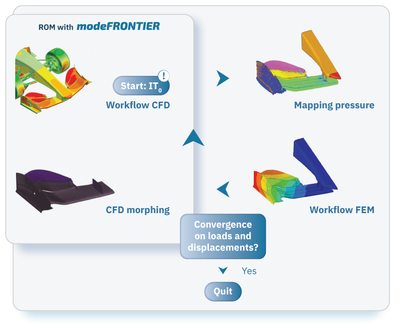
The modeFRONTIER workflow shown in figure 1 highlights how the various stages of the FSI cycle are integrated.
The iterative process follows these main steps:
- Structural simulation – Apply a pressure load derived from a preliminary CFD analysis of the undeformed wing to the structure.
- Mesh morphing – Use the resulting deformation field as input to update the front-wing surface mesh and reflect structural deflection.
- Fluid-dynamic simulation – Feed the morphed CFD mesh into a new simulation to compute the updated pressure distribution.
- Iteration – Pass the updated pressure field and deformed FEM mesh into the next structural cycle.
- Convergence check – Repeat the process until convergence between aerodynamic and structural results is achieved.
- Data collection – For each iteration, collect both the deformation and pressure fields relative to the deformed geometry to form the dataset used for ROM training.
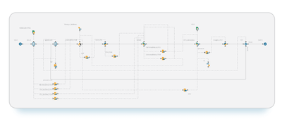
Figure 1: modeFRONTIER workflow for FSI process automation.
modeFRONTIER for ROM training and prediction
In order to build a ROM capable of predicting the pressure field as a function of the deformed geometry, it is required to characterize each deformation field through the geometry encoding.
The data set solutions, consisting of the displacement field for each front wing design, are rearranged into a matrix that can be expressed by proper orthogonal decomposition (POD) as a linear combination of coefficients and modes. These modes are ranked based on their energy contribution, with the first few modes capturing most of the dataset’s variance.
By truncating the basis and keeping only the most significant modes, we obtain a compact yet informative representation of the deformation behavior. The resulting POD coefficients serve as the encoded parameters, which are essential for the ROM training phase.
This encoding step is carried out within modeFRONTIER using the ROM encode connector (as shown in figure 2). The pressure fields and the parameters derived from the encoding process, constitute in fact the fundamental data set for training the reduced model.
ROM training and validation workflow:
- Apply POD to pressure fields to approximate high-dimensional pressure data and reduce it into principal modes.
- Interpret pressure POD coefficients as functions of the previously derived encoding parameters from geometry deformation.
- Train a regression model to predict pressure POD coefficients for unseen wing geometries. Common techniques include radial basis functions, Gaussian processes, and neural networks.
- Reconstruct the pressure field as a linear combination of pressure POD modes weighted by the predicted coefficients.
- Implement and validate the model in modeFRONTIER using the ROM Train connector. The dataset is split into training and validation sets, and model accuracy is assessed by comparing predicted pressure fields with the original simulation results.
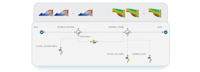
Figure 2: modeFRONTIER workflow for ROM training.
Deploying and validating the ROM predictions
Once the ROM quality is deemed satisfactory, it can be deployed using the pPredict connector to efficiently estimate pressure fields for new wing configurations. The connector can be integrated in the original workflow, substituting the computationally intensive CFD simulation.
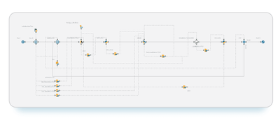
Figure 3: modeFRONTIER workflow for ROM prediction.
A new combination of wing material properties is created in order to test the ROM-FEM coupling. The predicted pressure fields for the two first iterations of the cycle are visible in figure 4, where it is possible to observe the good agreement among the pressure distribution computed by the CFD model and the one predicted by ROM.
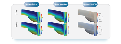
Figure 4: Pressure distribution computed by the CFD model and the one predicted by ROM.
This case study has demonstrated the feasibility of replacing the CFD process with a reduced-order model within a fluid-structure interaction cycle. , delivering major benefits:
- computation time: Reduced from a 15-minute FSI cycle on 350 cores to near-instant results on a single core,
- efficiency: Significantly lower computational costs while maintaining model accuracy,
- scalability: The next goal is to extend ROM integration to the entire open-wheel race car for full FSI simulation efficiency.
Conclusion
The Ferrari and Dallara case studies show how multidisciplinary design optimization (MDO) and reduced order models (ROM) accelerate automotive innovation. With modeFRONTIER, both teams streamlined simulation workflows, reduced computation time, and enhanced design accuracy — proving how automation and data-driven methods can turn complex engineering into faster, smarter decision-making.
Key takeaways:
- MDO links multiple engineering disciplines for better design trade-offs,
- ROMs replace heavy CFD runs with near-instant predictions,
- modeFRONTIER automates simulation and data exchange,
- Ferrari and Dallara achieved faster, more efficient workflows,
- data-driven models enable smarter, scalable engineering.
People also ask
MDO is an engineering approach that integrates multiple disciplines—such as structural mechanics, aerodynamics, and thermodynamics—into a single optimization process. It helps engineers find the best overall design by balancing performance trade-offs across systems.
A ROM is a simplified mathematical model that approximates the behavior of high-fidelity simulations like CFD or FEM. It delivers results almost instantly, allowing engineers to explore many design variants without running time-consuming simulations.
modeFRONTIER automates complex simulation chains and integrates tools such as CFD, FEM, and data analytics. Its AI-driven ROM connectors (Encode, Train, and Predict) help users build and validate predictive models directly within an automated workflow.
Ferrari improved F1 power-unit efficiency through automated CFD optimization, while Dallara accelerated its FSI analyses using ROMs built in modeFRONTIER. Both achieved faster design iterations, lower computational costs, and fewer physical prototypes.
Automotive engineers can benefit from our software solutions VOLTA and modeFRONTIER to innovate the simulation-driven product development and achieve better vehicle designs with increased performance at reduced production costs.
Validate automotive design, autonomous and e-mobility system with our technology.
Automotive engineers can benefit from our software solutions VOLTA and modeFRONTIER to innovate the simulation-driven product development and achieve better vehicle designs with increased performance at reduced production costs.