
Optimizing gas turbine rotordynamics: a robust design approach for vibration analysis
Written by Saurabh Sharma, Nils Wagner and Tobias Gloesslein

When engineering cutting edge products, not every design parameter can be padded with a deterministic factor of safety. This can result in an over-engineered product with heavier and more expensive components. On the other hand, the designs that function well in a deterministic setup (e.g., spherical cows in a vacuum), could break down the moment real-world chaos hits them.
Even with a relatively simple beam-model of a gas turbine, determining the non-linear relation between a combination of the factors and the respective response can be complex. Therefore, instead of relying on one approach for design conception, engineers can wrap the structural skeleton of a deterministic, physics-based design with stochastic methods in a probabilistic skin.
Beyond deterministic critical speeds: designing for real-world uncertainties
Campbell diagrams are used to determine the ideal operation ranges for which the natural frequencies of a gas-turbine system do not match the operating speeds or excitation orders. The points where the matches happen are known as the critical speeds or frequencies which are to be avoided in an ideal design and operation of the turbine.
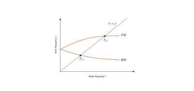
A typical Campbell diagram.
However, in the real world these theoretically ideal designs are additionally subjected to vastly different temperatures, material microstructures, machining tolerances, and other, possibly unaccounted, operating conditions. Accounting for uncertainties results in designs that are more resilient to the alteration or loss of functionality and performance under most circumstances. Once these uncertainties are adopted in vibrational design by a Rotordynamics Engineer, non-domain experts in NVH/vibrational design such as a Design Engineer could turn the results from this exercise into safer design choices about rotor diameters and turbine operating ranges. In this scenario, a simulation process and data management (SPDM) framework like VOLTA could be useful for cross-functional engineering teams: SPDM stores the rotordynamics model and automates the related simulations so that design engineers can quickly and reliably choose rotor geometries and operating ranges that are statistically safe, with full traceability of how those decisions were made.
Simulating rotor variations and creating campbell diagrams with PERMAS
PERMAS is a high-performance finite element analysis (FEA) software optimized for large-scale models and offers fast solution times through efficient solvers and advanced parallelization techniques. Since it supports a wide range of physical analyses within a single unified environment, including vibrations and acoustics (including fluid-structure interaction) and linear and nonlinear dynamic analysis, it’s particularly suitable for complex engineering simulations.
We used a beam-model of a 5-kN, single spool, thrust turbine design created in PERMAS. The geometry, frequency loads, constraints and the bearing stiffness matrices can be quickly set up in PERMAS’ pre-processor VisPER.
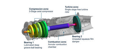
FE Model set-up of the gas turbine in PERMAS.
In this study, the outer diameters of the compressor and turbine rotors are varied while keeping the rest of the boundary and initial conditions unchanged.
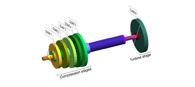
Geometry input parameters of the PERMAS FE model.
The results from the PERMAS simulation are the rotor-shaft system’s natural frequencies which are then plotted on the Campbell diagram against the excitation frequency of the system using Python.
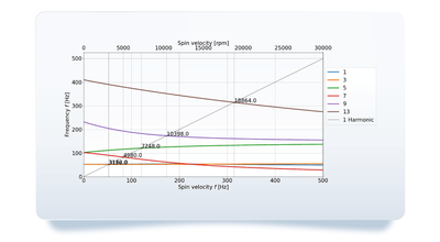
Campbell diagram created in Python for one of the design configurations.
These natural frequencies can be classified as forward and backward whirls (FW and BW), depending on their precession direction. Then, the synchronous excitation line is overlaid on the Campbell diagram and the intersection points where the rotor-shaft system’s rotational frequency matches the natural frequencies are identified as the critical speeds. This post-processing step is also undertaken via Python.
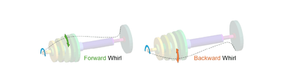
Forward and backward whirls relative to the direction of rotation of the shaft (blue).
When approaching the above steps manually or through a script, the Rotordynamics Engineer will need to do the following for each design iteration:
- change the diameters of the compressor and the turbine rotors,
- carry out the simulations of the updated geometries,
- run the Python script to: calculate the intersection of the synchronous excitation line with the natural frequencies; plot the critical speeds on the Campbell diagram.
This workflow results in a total of six critical speeds denoted as 1FW, 1BW, 2FW, 2BW, 3BW, and 4BW at the respective whirl modes for the rotor-shaft system. The numbering denotes different vibration modes, while FW and BW indicate forward and backward whirl behaviour respectively.
Accelerating vibration simulation analysis with ESTECO software
1. Automate PERMAS simulations into the modeFRONTIER workflow
The above steps can be actionized in modeFRONTIER’s simulation workflow using the PERMAS connector. VisPER’s sampling wizard is used to create a PERMAS control file with the task loop that will be run by modeFRONTIER after changing the input values of the rotor diameters in the model. In VisPER’s sampling wizard, the desired parametrization of the Design Elements must be defined by the Design Variables. Optionally, the default values and the upper and lower bounds can be defined, which can then be directly read into modeFRONTIER from the model files.
Such workflow automation can support multidisciplinary design optimization (MDO) studies where multiple objectives, constraints and engineering domains must be evaluated simultaneously.
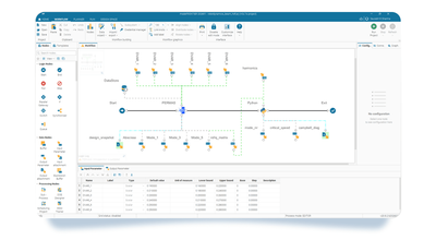
PERMAS preprocessing, simulation, and postprocessing workflow in modeFRONTIER.
During the introspection of the PERMAS model in modeFRONTIER, data from the control file, the model files and the results are translated into the input and output parameters. From the results, a matrix with all the natural frequencies can be selected to be transferred to the Python node for operation by the subsequent nodes in the process. This Python node is automatically executed as part of the simulation workflow and creates a Campbell diagram for the given set of rotor diameters.
After the main input and output parameters, their flow and the process is developed in modeFRONTIER by a Rotordynamics Engineer, the workflow is ready to be uploaded to VOLTA digital engineering platform.
2. Scale and democratize PERMAS simulations with VOLTA
The modeFRONTIER’s simulation workflow can be shared with teams or individuals and executed on selected computational resources using VOLTA digital engineering platform. The simulation workflow model, now part of a VOLTA project, also points to all the files necessary for it to run (its dependencies), such as the control file, the model files and the Python script. Any execution of the simulation process from VOLTA creates a snapshot of all of these dependencies. This way the Rotordynamics Engineer is always able to tell which versions of the dependencies and workflow were used to generate which results. This level of traceability is critical in today’s engineering world and especially important in a collaborative environment.
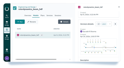
Workflow in VOLTA with the information on sharing, ownership, and version control.
To determine the general behaviour of the system, an initial design of experiments (DOE) study is carried out in VOLTA with the rotor-diameter Design Variables in meters (m) as input parameters and the critical speeds in Hertz (Hz) as output parameters. The diameter values are sampled in the entire design range, resulting in a dataset that can be analyzed to gain initial understanding of the system.
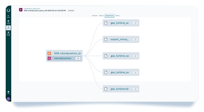
Dependency of a simulation session in VOLTA with a snapshot of the used versions of the input files.
Using the results of this initial DoE, a sensitivity analysis between the input rotor diameters and the output critical speeds at respective modes is undertaken in VOLTA. The influences on critical speeds whose dependencies are spread over several rotor diameters is hence quantified in a correlation matrix.
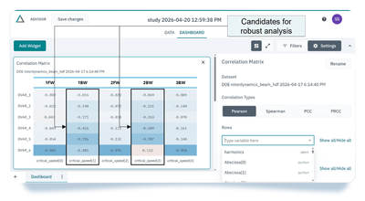
Pearson correlation analysis in VOLTA Advisor.
The correlation matrix chart shows that the critical speeds for the 1BW and the 2BW modes are dependent on almost all the rotor diameters. Hypothesisation of the influence of a single or a combination of rotor-diameter variations on these critical speeds is difficult, if not impossible. Hence, these critical speeds are selected for the Robust Design Explorations.
3. Conduct robust design exploration with VOLTA
Robustness is the ability of a system's responses to remain insensitive to variations of input parameters and variations in their operating environment with minimal alteration or loss of functionality. This technique additionally accounts for the robustness of the design combinations defined by the rotor diameters in the parametric input region of interest. By employing the robustness and reliability domain in VOLTA where the designs defined by the combinations of the rotor diameters are the nominal designs and can additionally be checked for robustness in the critical speeds at the 1BW and the 2BW modes. Under this analysis, VOLTA samples additional points in the vicinity of the nominal design point as per a selected distribution.
These additional points can be sampled using the Latin Hypercube-Monte Carlo sampling. This mode of constrained sampling splits the distribution into several intervals with the required probability and samples one design point per interval.
For example, for a normal distribution around a nominal design point, the mean of the distribution is just the nominal design point defined by the diameter values. The standard deviations of the diameter values around the nominal design points are determined by:
- manufacturing tolerances,
- thermal effects,
- material properties.
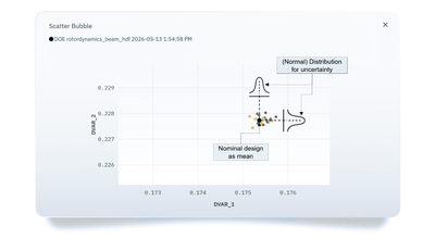
Uncertainty in the rotor diameters for 1st and 2nd stage compressor rotors.
Constraints on the output parameters are added to as well to identify the designs violating requirements due to the deviations in the inputs. Robustness of the nominal design can be inferred from the number of unfeasible designs in yellow. Occurrence of a number of yellow designs would mean that, given a standard deviation in the distribution of the input diameter values with the nominal design as the mean, the critical speed fluctuates more than the acceptable tolerance.
In this manner, any of the designs in the region of interest can be checked for robustness. The robust designs are those for which none of the designs from their extended region of uncertainty violates the respective constraints.
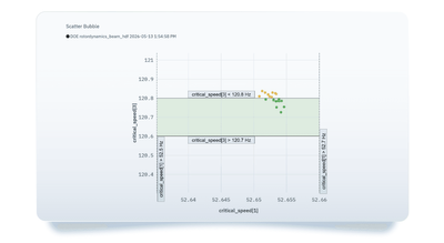
Distribution of the resulting critical speeds at 1BW and 2BW modes.
Key takeaways
- Anyone on the engineering team (for example, the Design Engineer) can run the workflow on VOLTA to: evaluate safer operating ranges, identify sensitivities and explore new design variations.
- Team permissions and access are carefully controlled. Design Engineers can run the workflow, view and download results, but cannot modify the workflow. Rotordynamics engineers can see who used their workflow, when and how. This can help identify misuse of the model (e.g. outside of its intended domain), problems with the process and possible avenues for improvement.
- In the process of Robust Design, we leave the comfort of a “guaranteed” safety factor and venture into the transparency of calculated risks. The team embraces uncertainty, designs around it and shares cross‑disciplinary knowledge of the experts from several aspects of engineering design.
- Stochastic models are always based on data and an event that has never happened before can still occur (Black Swan). The question is: if it occurs, would you rather trust just the physics analysed in the model, or the physics in the model validated for robustness under uncertainty?
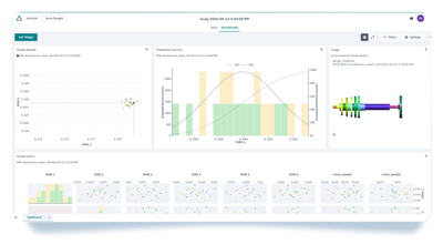
Sharable VOLTA Dashboard with multiple studies including the image of the model.
Nils has been a key member of the Pre-Sales Department at INTES since 2011. He holds a Master’s in Mechanical Engineering and a PhD in Civil Engineering, supplemented by post-doctoral research in parameter-dependent eigenvalue problems at the University of Stuttgart. At INTES, Nils leads training courses on VisPER and optimisation, and is responsible for benchmarking and conference papers, drawing on his expertise in the PERMAS FEA package and the VisPER pre- and post-processor. While his work spans all aspects of CAE with a particular focus on structural dynamics, rotor dynamics, and optimization, he is currently dedicated to the PERMAS for Education (PERMAS4EDU) initiative.
Nils has been a key member of the Pre-Sales Department at INTES since 2011. He holds a Master’s in Mechanical Engineering and a PhD in Civil Engineering, supplemented by post-doctoral research in parameter-dependent eigenvalue problems at the University of Stuttgart. At INTES, Nils leads training courses on VisPER and optimisation, and is responsible for benchmarking and conference papers, drawing on his expertise in the PERMAS FEA package and the VisPER pre- and post-processor. While his work spans all aspects of CAE with a particular focus on structural dynamics, rotor dynamics, and optimization, he is currently dedicated to the PERMAS for Education (PERMAS4EDU) initiative.
People also ask
Deterministic safety factors help account for uncertainty by adding margins to a design. However, they do not show how variations in manufacturing tolerances, material properties, or operating conditions influence performance. As a result, engineers may overdesign components or miss combinations of variables that increase vibration risks. Robust design methods complement deterministic analysis by evaluating performance across distributions of possible conditions rather than single scenarios.
In multidisciplinary projects, design engineers often need access to simulation results but not permission to modify validated workflows. Digital engineering platforms can separate execution rights from editing rights, allowing teams to run simulations, compare results, and reuse approved processes while maintaining traceability and governance. This approach helps reduce errors and improves collaboration between domain experts and non-experts.
Teams looking to improve simulation process and data management, workflow traceability, and cross-functional engineering collaboration can explore how simulation process and data management capabilities for engineering workflows support controlled access and reproducible simulation studies.
Manual execution may be sufficient during early studies with few design variations. However, automation becomes valuable when engineers need to evaluate many parameter combinations, run DOE studies, perform sensitivity analyses, or repeat simulations across changing requirements. Automating workflows can reduce repetitive work, improve reproducibility, and accelerate design exploration.
Engineers evaluating simulation workflow automation, design optimization, and integration across multiple CAE tools can learn more about engineering workflow automation and multidisciplinary design optimization solutions for scaling complex simulation studies.
Robust design approaches can also be applied in aerospace, automotive, energy, and manufacturing environments where performance depends on uncertain inputs. Examples include evaluating structural fatigue, optimizing thermal systems, reducing vibration issues, or studying reliability under changing operating conditions. The goal remains similar: identify designs that maintain acceptable performance despite variability.
Schedule a live demo tailored to your needs.
See modeFRONTIER and VOLTA in action
Schedule a live demo tailored to your needs.
See modeFRONTIER and VOLTA in action
Schedule a live demo tailored to your needs.